
Power-Smart Head Version 3
It’s been a while since I’ve built any BEAM robots, but some wet weather prompted me to get back to the soldering iron and make a new bot.

This is another solar powered “power-smart” head, built around a 74AC240 chip. The circuit is the Solar Power Smart Head circuit. The motor is a nice geared 141:1 MicroMo motor I got off Ebay. It has a cog attached to the spindle, which allowed me to mount it in a drilled-out hard drive part for the base.
This guy fires every few seconds under bright light, and almost continuously in daylight, rotating quite quickly, and smoothly to point towards the brightest part of the environment. I’m pleased with it.
permalink | robots | 2009.01.25-17:20.00
Symet
The Symet use one of the simplest BEAM circuits. The solar cell charges the capacitors (one or more in parallel). A solar engine circuit monitors the voltage, and when it trips power is dumped through the motor. Symets rest on their motor spindle, and scoot long the ground when the motor spins. When they hit something, they tilt onto another axis, and go off in a different direction.
This is one of the first free-formed BEAM bots that I built. The circuit is a 1381-based solar engine circuit, and is built around the motor, with components placed radially around a central axis. I used a platter from a laptop hard drive as the bumper.
The trick with symets is to get the angle relative to the ground and the spindle ground contact right so that the symet moves in a straight line until it hits something. I failed with this one, but it jiggers around in circles quite happily. I also learnt that hot-glue solidifies instantly when it comes into contact with cold metal. Either use the tip of the hot glue gun to heat the metal before glueing, or use epoxy.
permalink | robots | 2007.11.19-22:31.00
Turbot
Turbots are BEAM bots that move by spinning flagella, causing them to tumble across the floor. The simplest are just motors driven by a solar engine, and have no directional ability; these are commonly known as a turmets. More complex turbots can move towards the light, reverse their motors to get out of tangles, and other things.
I played for a while with several turbot circuits, particularly those by J Wolfgang Goerlich (who has an excellent series of pages on various turbot designs). His Scuff turbot looked particularly promising, as it was solar powered, and had phototactic behavior.
However, I was also wanted to build a bot whose workings fitted neatly between two solar cells. That dictated the body shape (rectangular), which severely limited the behavior, since it’s hard to get turning if the axis of rotation for both flagella is the same. But I wanted something slightly more complex than a single-motor turbot.

The circuit I came up with is a simple modification of a 74AC240-based photovore design (but I wish I’d seen Wilf’s caveat about this circuit first!). First, it’s solarized with a Miller solar engine. Secondly, I wanted the circuit to choose which motor to drive based on which solar cell was getting more light (i.e. the bot knows which way is “up”). Since the bot has two solar cells, I could replace the photodiode voltage divider in that circuit with the solar cells themselves, by taking a reference voltage from between the two cells (which are wired in series), via a large resitor. Reverse-biased Schottky diodes across each solar cell ensure that the unlit cell doesn’t limit the charging current.
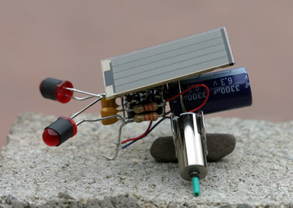
The innards of this beast are shown below. It’s pretty tightly packed! (Click the image for a larger view.)
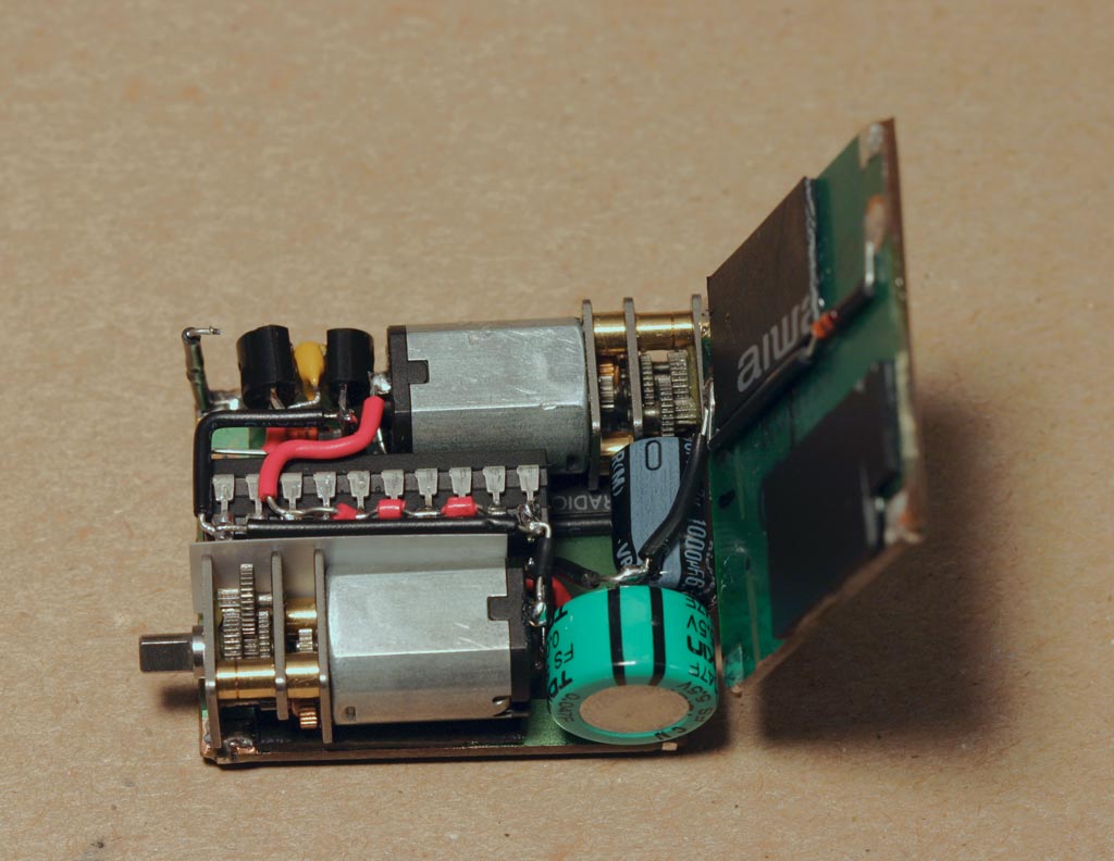
You can see the Miller SE in the top-left corner. There are two 74AC240s: doubled-up to increase the drive current for the motors. The main storage capacitor is 0.047F; on its own, it can’t dump enough current to reliably start up the gearmotors (which are GM11s from Solarbotics), so there’s another 1000µF capacitor in parallel to get things going. The whole thing is epoxied together, with some scrap plastic spacers to allow the gears to clear the solder pads on the solar cells.
This guy is pretty active in bright light, churning his way in straight line. It has a few issues, like it can end up balanced on one end, with neither cell getting much light (which could be fixed by adding some bumps to make it topple over), and the legs can hit each other. But the compact construction appeals to me.
permalink | robots | 2007.11.19-22:31.00
Solar Power-Smart Head
I experimented with a number of power-smart head circuits on the breadboard, but none seemed as simple and reliable as the bare-bones photo head. However, I wanted to try one of the power-smart heads, so went ahead and built this one.

This is a solarized power-smart head. It’s based on a 74AC240, with two storage capacitors (the big silver cylinders), and photodiodes for “eyes”. The solar engine is free-formed to lie over the IC. The motor is a Nihon gear motor from a lens assembly (courtesy of Fair Radio Sales), epoxied into a base made from hard drive motor parts.
This head works pretty well, but looks a bit ugly. It’s harder to position the components around the cylindrical motor than the nice cuboidal Omron units.
permalink | robots | 2007.11.19-22:31.00
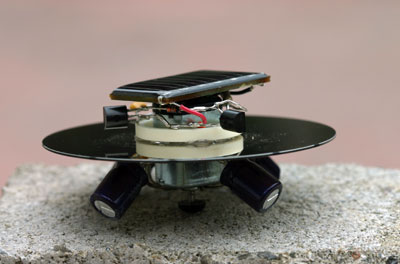
Spinner

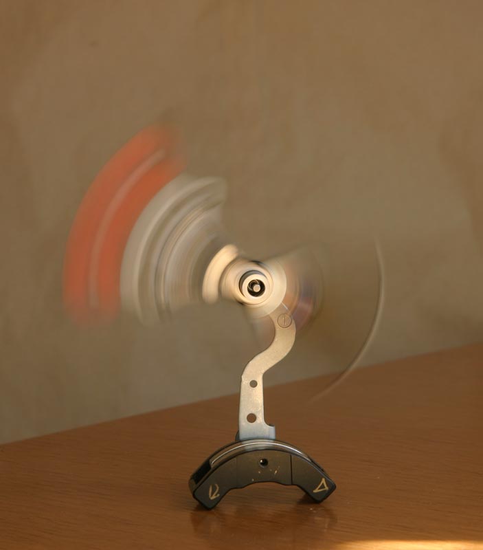
The spinner is a very simple bot that simply charges up the capacity (the green squat cylinder in the image) via the solar panel, which then discharges through the motor when a certain voltage is reached. This is exactly the same circuit as the symet (with some adjustment of component values), but the bot is configured “standing on its head” so that the head spins around when the motor fires.
This was a fairly easy robot to build. One thing to be aware of is that when you have your circuit on the breadboard, running a motor with no load, the motor will spin for much longer than it does under load. I had to retrofit a larger timing capacitor on the Miller engine to have this guy spin for a reasonable amount of time on each charge. You can see the solar engine here:
The copper loops are actually large C-clips from some large (projector or copier) lens assemblies, hot-glued onto the motor body, and soldered to eachother.
permalink | robots | 2007.11.19-22:31.00
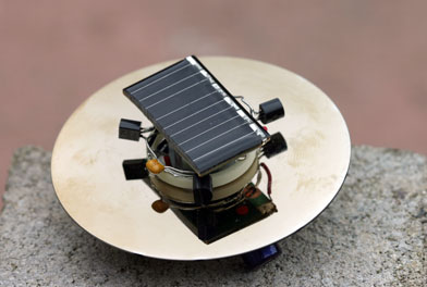
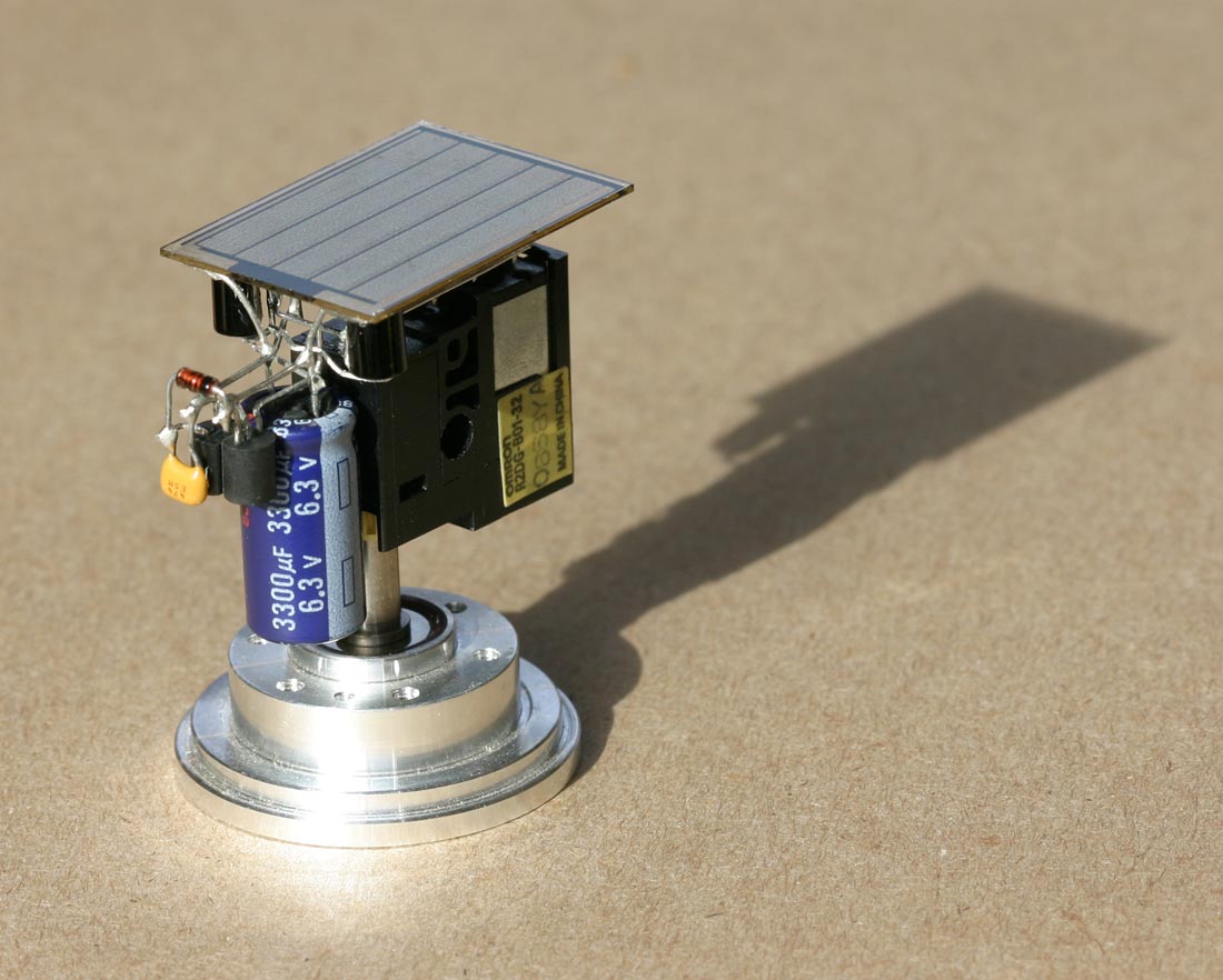
Solar Head
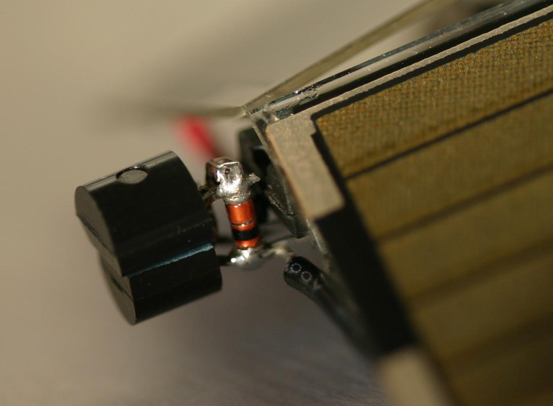
This is my third attempt at a solar head, again using a Nihon gear motor like my second one. I was trying to improve the aesthetic, as well as experimenting with the Power Smart Head Version 3 circuit. I couldn’t get the latching SE to work very well in that circuit, so I modified the circuit to use a standard Miller solar engine, and was thus able to use the spare inverters to help drive the motor.
Unfortunately, this beast needs very bright light to work well, so it needs direct sunlight to perform at its best. I might try it with a lower voltage trigger at some point.
permalink | robots | 2007.11.19-22:31.00
Roller
This bot is my first experiment with flexible solar cells. Although not as efficient as the cells used in most BEAM bots, the flexibility of these cells allows for some novel bot configurations.

The bot is a simple solar roller, driven by a Miller solar engine. The arm is attached to the spindle of an efficient gear motor, and there’s a 0.047F storage capacitor inside. The flexible solar cell is wrapped around two toy wheels, one of which has its center removed for the motor. The goofy rubber tires fit over the ends. You can see the bot’s innards here.
In full sunlight, this bot fires every few seconds, which more often than I thought it would given that only a proportion of the cell is getting direct light. It can also clamber over low obstacles.
permalink | robots | 2007.11.19-22:31.00
Solar Photopopper
The Bare Bones photovore is a beautifully simple circuit that makes use of the fact that the switching voltage of the inverter inputs on the 74AC240 is roughly half the supply voltage. The circuit uses a pair of photodiodes as a voltage divider. The mid point of the divider is converted to a “high” or “low” signal by the inverter, which is used to determine which of two motors to run.
I’ve been toying with the idea for a while of using two solar panels in place of the photodiodes, and simply taking a mid-point voltage reference to figure out which panel is getting more light. Then, given the appropriate configuration of solar panels and motor wiring, it should be easy to make a bot that heads towards the light with no photodiodes. This is the result (with schematic this time!).


Its body is the 74AC240 chip, with a capacitor abdomen. The head is the Miller solar engine, which uses a couple of surface mount components; an old SMT diode, and a tiny capacitor, both salvaged from old circuit boards:
This guy works well. It’s a little slow to pop if the light is only hitting one panel, but takes very few pops to orient itself towards the light. Once both panels are getting equal illumination, both motors pop and it goes forwards.
permalink | robots | 2007.11.19-22:31.00
BEAM robots
BEAM robots are simple, small robots whose behaviors are inspired by biological phenomena. They are largely the brain-child of Mark Tilden, who developed most of the core circuits. They use commonly available electronic components, including some analog ICs, and most are solar powered.

BEAM is an acronym for “Biology, Electronics, Aesthetics, and Mechanics”, which describes the major influences on BEAM robot designs.
permalink | robots | 2007.11.19-22:31.00
Magbot Spinner
The magbot circuit is neat little circuit that dumps power through a coil in order to produce motion. It’s the basis for the Solarbotics SunSwinger pendulum kit, and various “sun dancer” kits.
I wanted to make a bot with this circuit that could swing a full 360°, using some hard drive magnets and the Solarbotics “Major Henry” coil. My first attempt used a stripped CD-ROM motor for the axle, but that had too much damping (even after removing the magnets). I ended up using a VCR pinch roller, which has a very free-rotating bearing (but had to be laboriously stripped of its rubber wheel).
I was lucky to find a hard drive magnet pair in a frame, from an older hard drive. The vertical chassis is from an old VCR. The body of the rotating part is a hard drive head mechanism, which happened to fit nicely over the pinch roller hub. The circuit is mounted on this arm, with some care taken to balance it so that the arm can swing all the way around given enough force.

This is a fun bot to watch. In bright light, it starts swinging almost immediately, and after a few swings just makes it to the top, then over. After that it’ll keep rotating all the way around.
permalink | robots | 2007.11.19-22:31.00
Power-Smart Head Version 2
After re-reading Wilf’s BEAM Heads 101 I had the urge to make another head. I also wanted it to have more “presence” that my previous heads, which meant that it had to be more obvious when it turned around, and hence less symmetrical. I happened to have some parts lying around that I could use to make such a bot.

A defunct laser disk player provided the motor and gears; it’s the assembly that flips the read head from one side of the disk to the other. A nice large solar panel allows the bot to run under reasonably bright indoor lighting, and the usual pair of photodiodes are tucked under the solar panel. The base is a chunk of steel that held the head magnets on a big old hard disk, and is heavy enough so that the whole thing doesn’t fall over.
The circuit is the basic power smart head circuit, with a Miller solar engine. Since I was using a separate SE, I could gang two sets of three inverters each to drive the motor. I actually used a 74HCT240 by mistake (meant to use an HC240), but it seems to work pretty well anyway!
permalink | robots | 2007.11.19-22:31.00
Dual LED Pummer
A pummer is a BEAM robot that absorbs solar energy during the day (by charging up a large capacitor or rechargable battery from a solar panel), and releases it during the night, usually by blinking one or more LEDs. Think of it as a robot “plant”. The trick here is to get a circuit that is energy efficient (so can blink the LEDs for as long as possible once it gets dark), and blinks the LEDs in interesting ways.


This a pummer that I built. It’s a dual LED pummer, based on a bicore circuit using a 74HCT240 chip. The circuit is described at the Solarbotics site (see schematic for a similar design that uses recharable batteries in place of the capacitor).
The frame of the pummer consists of three hard drive spacers; two for the base (a thin dark one on top of a larger aluminum one), and one placed vertically. Both the HCT240 and the 1F storage capacitor just fit inside their respective rings, which inspired the design.
The LEDs are super-bright blue and green. Because these suck up a fair amount of juice, this pummer only runs for about an hour after dark.
permalink | robots | 2007.11.19-22:31.00
Solar Herbie
The Herbie isn’t strictly a BEAM bot, but it follows the BEAM tradition of using ICs for purposes they were never intended for. The Herbie circuit is based on the LM386 integrated circuit, which is normally used as an audio amplifier. In the Herbie circuit, the chip is used to amplify the difference between the outputs of a couple of photodiodes, giving the bot phototactic behavior.

Here’s my Solar Herbie. It’s the standard Herbie circuit, with a Miller solar engine. The LM386 is tucked above the blue trim pot (I flattened the pins to make it sit flat). The small motors are from laptop CD-ROM drives, and the solar engine is positioned between the motors and the capacitor.
permalink | robots | 2007.11.19-22:31.00
FLED Photopopper
FLED photopoppers make use of the property of flashing LEDs (FLEDs) that they are photosensitive; they consist of a pair of coupled solar engines with FLEDs as photodetectors.
I built this photopopper following Ray’s FLED Photopopper Tutorial, but I mounted my gang of transistors upside-down so that it looks nicer from the bottom. The results are quite pleasing, and this is quite an active little guy. He’s the first to start popping when the sun hits my robot collection. The only problem is that he’s liable to fall onto his arse; either the motors need to be placed further back, or there needs to be more weight towards the front. Oh, and I’ll clean up those motor leads one of these days.
permalink | robots | 2007.11.19-22:31.00
Flatbot FLED Photopopper
This is a standard FLED photopopper made with a Sanyo solar cell, and a couple of motors salvaged from laptop CD-ROM drives (the motors that move the head back and forth across the disk surface).


The challenge here was to to fit everything neatly under the solar panel. This bot is quite active in sunlight, but doesn’t seem to be very phototropic.
permalink | robots | 2007.11.19-22:31.00
Dual Solar Panel Head
The solar photopopper replaced the two photodiodes of the bare bones photovore circuit with the solar panels, by taking a reference voltage from their mid-point. This technique was simple to apply to the bare bones head circuit too (with the modification suggested by Wilf Rigter here).
The result is a dual solar panel head, with no additional photodetectors.


Like my bare bones head, this robot uses an Omron floppy drive eject motor, with a base made from hard drive spindle motor parts. The circuit is switched by a Miller Solar Engine, and there are two 3300µF storage capacitors under the solar panels. I used some salvaged surface mount components for the solar engine capacitor and diode, which make the SE nice and small, as shown in the second photograph. The chip is a 74AC240. A schematic is available.
permalink | robots | 2007.11.19-22:31.00
Bare bones photo head
A BEAM “head” robot is a robot that can “look around” for the brightest source of light. This usually means mounting everthing on top of a gear motor, and then fixing the spindle of the motor to the base.
This is a bare-bones photo head which uses a 74AC240 IC, and two photodiodes as light detectors. It’s based on this schematic, which uses a Miller solar engine. You can see the free-formed solar engine overhanging the front of the capacitor; the IC is hidden under the solar panel.
The motor is an Omron gear motor obtained from a Mac floppy drive (it’s the motor that gives the Mac floppy drives their distinguishing feature—software eject). The base is made from parts of a hard drive motor.
This little guy chatters every second or so in the sun. It was my first well-functioning head, and I like the way it turned out.
permalink | robots | 2007.11.19-22:31.00
BEAMAnt
The BEAMAnt is a phototactic bot which has potentially complex behavior depending on the light level. It has two photodiodes for light sensing, and two antennae which switch the motors into reverse when they touch something.
The core of the BEAMAnt is a 74AC240 chip wired as two coupled bicores. The first “photo” bicore oscillates at a frequency and symmetry determined by the light falling on the photodiodes—slow in low light, and faster in bright light. The second “motor” bicore generates a basic left/right oscillation that is used to alternate the motors. The two bicores are coupled by resistors, which can lead to complex interactions between them. The circuit has two tactile sensors, which temporarily reverse the polarity of the motor on the other side. This allows the bot to turn away from obstacles.

This BEAMAnt is based on two small gear motors (Solarbotics GM15) on a bent paperclip frame. I solarized the circuit with a Miller solar engine, which you can see hanging off the back in the “under the hood” shot below. Most of the circuit is free-formed around the ‘240 IC; the two photodiodes sit underneath the front corners of the solar cell, and the 0.047F capacitor acts as a nose.

Initially, the bot just scooted forward on a skid made from the bent paperclip. However, on anything other than a very smooth surface, the bot wasn’t able to turn around. I solved this by hot-glueing a small bearing from a floppy drive stepper motor over the skid.
This bot has impressive phototactic abilities. If the light source is off to the side, it will turn on its axis until it’s facing the light, and then head straight towards it. Obstacle avoidance could use a bit of tuning; the sensor timers capacitors don’t work very well in a solar-driven bot, because the power keeps dropping away.
permalink | robots | 2007.11.19-22:31.00
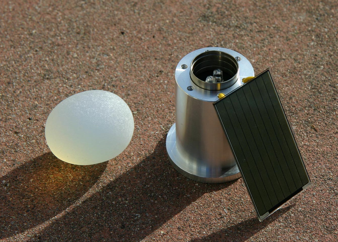
Egg Pummer
This is a dual LED pummer built using the standard 74AC240 pummer circuit. The electronics are tucked inside part of a hard drive spindle motor (from a big old hard drive), with the two LEDs illuminating the base of a glass egg.

Here’s a low quality movie taken with a Canon PowerShot of the pummer after dark (QuickTime 7 required):