Turbot
Turbots are BEAM bots that move by spinning flagella, causing them to tumble across the floor. The simplest are just motors driven by a solar engine, and have no directional ability; these are commonly known as a turmets. More complex turbots can move towards the light, reverse their motors to get out of tangles, and other things.
I played for a while with several turbot circuits, particularly those by J Wolfgang Goerlich (who has an excellent series of pages on various turbot designs). His Scuff turbot looked particularly promising, as it was solar powered, and had phototactic behavior.
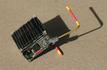
However, I was also wanted to build a bot whose workings fitted neatly between two solar cells. That dictated the body shape (rectangular), which severely limited the behavior, since it’s hard to get turning if the axis of rotation for both flagella is the same. But I wanted something slightly more complex than a single-motor turbot.

The circuit I came up with is a simple modification of a 74AC240-based photovore design (but I wish I’d seen Wilf’s caveat about this circuit first!). First, it’s solarized with a Miller solar engine. Secondly, I wanted the circuit to choose which motor to drive based on which solar cell was getting more light (i.e. the bot knows which way is “up”). Since the bot has two solar cells, I could replace the photodiode voltage divider in that circuit with the solar cells themselves, by taking a reference voltage from between the two cells (which are wired in series), via a large resitor. Reverse-biased Schottky diodes across each solar cell ensure that the unlit cell doesn’t limit the charging current.
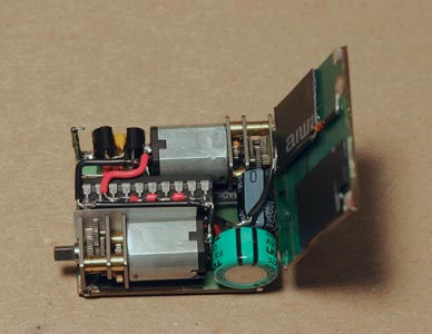
The innards of this beast are shown below. It’s pretty tightly packed! (Click the image for a larger view.)

You can see the Miller SE in the top-left corner. There are two 74AC240s: doubled-up to increase the drive current for the motors. The main storage capacitor is 0.047F; on its own, it can’t dump enough current to reliably start up the gearmotors (which are GM11s from Solarbotics), so there’s another 1000µF capacitor in parallel to get things going. The whole thing is epoxied together, with some scrap plastic spacers to allow the gears to clear the solder pads on the solar cells.
This guy is pretty active in bright light, churning his way in straight line. It has a few issues, like it can end up balanced on one end, with neither cell getting much light (which could be fixed by adding some bumps to make it topple over), and the legs can hit each other. But the compact construction appeals to me.
